<assembly.drawing.partview />
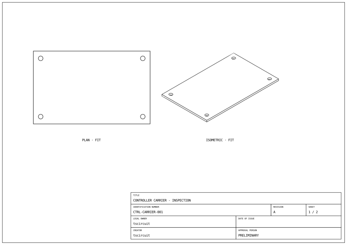
assembly.drawing.partview selects a board or mechanical part and places a view of it inside an assembly.drawing.page. The example places an isometric view to the right of the carrier's plan view.
import { assembly } from "@tscircuit/core"

export default () => (
  <assembly.device name="controller">
    <board name="carrier" width="80mm" height="50mm" thickness="1.6mm">
      <hole name="H1" diameter="3.2mm" pcbX={-35} pcbY={-20} />
      <hole name="H2" diameter="3.2mm" pcbX={35} pcbY={-20} />
      <hole name="H3" diameter="3.2mm" pcbX={35} pcbY={20} />
      <hole name="H4" diameter="3.2mm" pcbX={-35} pcbY={20} />
    </board>
    <assembly.drawing.page name="carrier-inspection" size="iso_a4">
      <assembly.drawing.partview
        partRef=".carrier" name="plan" displayName="PLAN"
        direction="z+" width="110mm" height="85mm"
        centerX="-70mm" centerY="30mm"
      />
      <assembly.drawing.partview
        partRef=".carrier" name="overview" displayName="ISOMETRIC"
        direction="isometric" width="110mm" height="85mm"
        rightOfRef=".plan" centerY="30mm"
      />
      <assembly.drawing.titleblock
        title="CONTROLLER CARRIER - INSPECTION"
        identificationNumber="CTRL-CARRIER-001"
        revisionIndex="A" legalOwner="tscircuit"
        creator="tscircuit" approvalPerson="PRELIMINARY"
        sheetNumber={1} numberOfSheets={2}
      />
    </assembly.drawing.page>
    <assembly.drawing.page name="carrier-section" size="iso_a4">
      <assembly.drawing.partview
        partRef=".carrier" name="section" displayName="SECTION THROUGH H3 AND H4"
        direction="y+" width="220mm" height="65mm" centerY="25mm"
        section={{ axis: "y", offset: "20mm", keepSide: "less", hatchSpacing: "1mm" }}
      />
      <assembly.drawing.titleblock
        title="CONTROLLER CARRIER - MOUNTING HOLE SECTION"
        identificationNumber="CTRL-CARRIER-002" revisionIndex="A"
        legalOwner="tscircuit" creator="tscircuit"
        approvalPerson="PRELIMINARY" sheetNumber={2} numberOfSheets={2}
      />
    </assembly.drawing.page>
  </assembly.device>
)
Properties
| Property | Description |
|---|---|
partRef | Selector for exactly one board, assembly group, or part, such as ".carrier". Selection is scoped to the containing assembly. |
stageRef | Selector for one reusable assembly.drawing.stage, such as ".rotor". Provide exactly one of partRef or stageRef. |
name | View name used by sibling placement selectors. |
displayName | Optional caption; otherwise the view's name is used. |
direction | Required: "x+", "x-", "y+", "y-", "z+", "z-", or "isometric". Axis directions describe where the camera is, looking toward the part. |
width, height | Required viewport dimensions on paper, in millimetres or unit strings. The exporter fits the selected geometry into the viewport. |
centerX, centerY | Viewport center relative to the page's anchorAlignment. Default: 0 on each axis. Positive X is right; positive Y is up. |
leftOfRef, rightOfRef | Place beside a sibling view using a selector such as ".plan". This infers centerX. |
aboveRef, belowRef | Place above or below a sibling view. This infers centerY. |
showHiddenEdges | Draw hidden edges as dashed lines. Default: false. |
section | Optional cut plane; see below. |
children | Optional dimension, partlabel, and note annotations. |
Paper coordinates do not move the model. Model directions and section planes use CAD world coordinates: millimetres, +Z up.
Relative placement
Relative placement makes the two viewport edges meet, using both views' dimensions. It does not align their visible geometry bounds or add a gap. Use an explicit center on the other axis when aligning views:
<assembly.drawing.partview
  partRef=".carrier" name="side" direction="x+"
  width="60mm" height="85mm"
  rightOfRef=".plan" centerY="30mm"
/>
Choose either an explicit center or a relative reference for each axis. Sibling references can point forward to a later view. Self-references, ambiguous selectors, and placement cycles are errors.
Section views
<assembly.drawing.partview
  partRef=".carrier" name="section" displayName="CENTRAL SECTION"
  direction="y-" width="110mm" height="40mm"
  centerX="-70mm" centerY="-35mm"
  section={{ axis: "y", offset: "0mm", keepSide: "less", hatchSpacing: "1mm" }}
/>
axis is "x", "y", or "z". offset places the cutting plane on that axis in CAD world millimetres. keepSide="less" retains coordinates below the offset; "greater" retains coordinates above it. hatchSpacing controls the diagonal hatch spacing in CAD model millimetres.
Views produce outline SVGs through tsci export. Their FIT caption indicates automatic fitting; do not infer a manufacturing scale or dimensions from the viewport size.
Dimensions
Add assembly.drawing.dimension children to annotate physical measurements. For example, widthOfView measures the selected geometry's width, while paired fromRef and toRef selectors measure hole spacing or an edge-to-hole offset. Anchors are optional and inferred from the referenced geometry.
Assembled subassemblies
Use stageRef=".rotor" to draw a reusable selection of assembled parts. See assembly.drawing.stage for composing parts, boards, and nested stages. To show a separated pose inherited from assembly moves, use assembly.drawing.explosionview. Both view types can be targets of sibling placement references on the same page.